


Fothelia is an ecosystem for controlling LED strips without any internet bridge, just by Bluetooth connection.
You will need some parts and you're going to need to do a bit of very simple tinkering to take control of the LED strip, but believe me, it will STILL cost you less than buying extension kits — when all you wanted was to use the leftover piece of strip that's been sitting in your closet...
By the end your controller device should be looking like this :
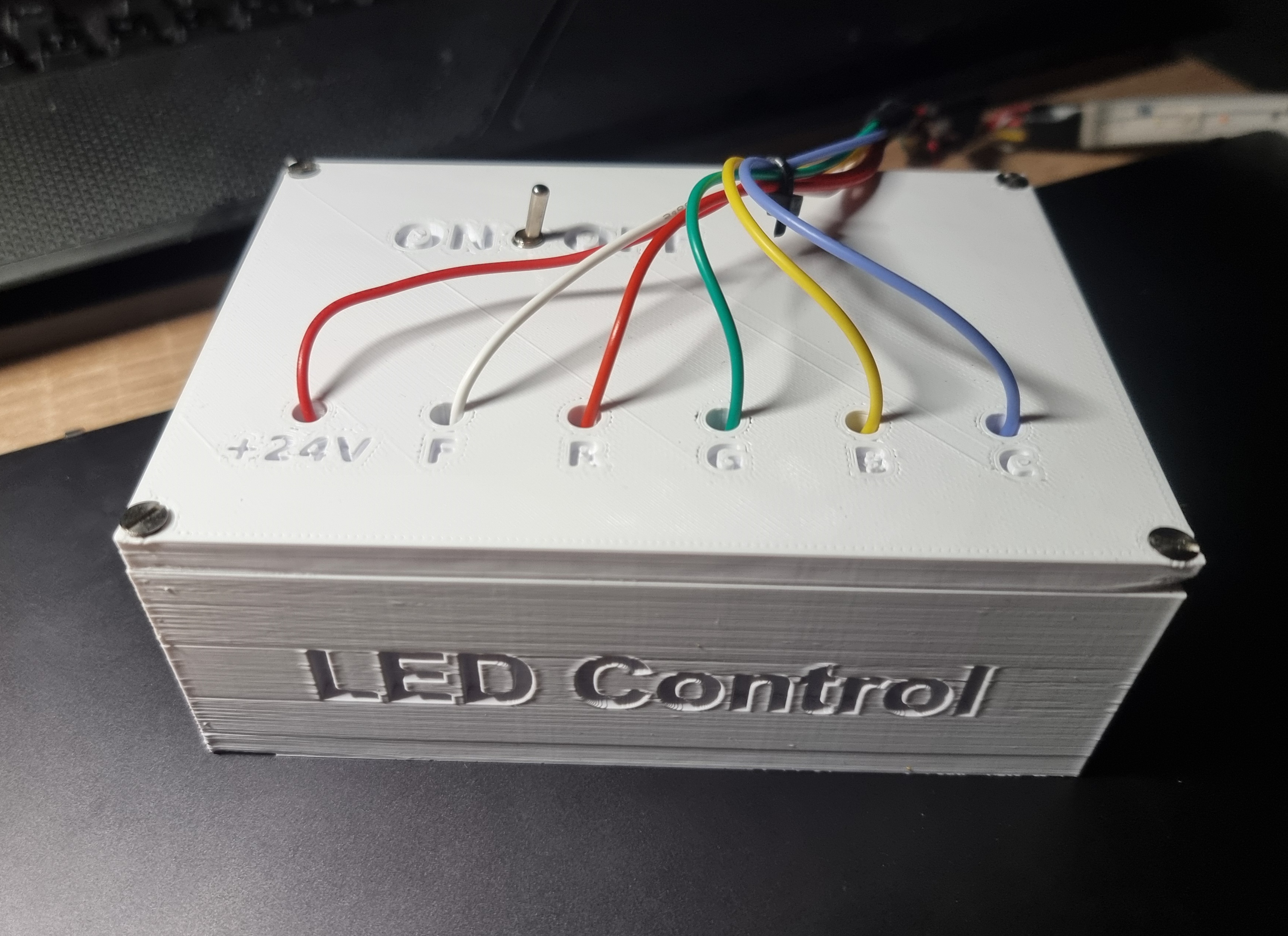
If you can print the enclosure with a 3D printer, the following CAD project files are available in the CAD directory. The box can be big since the Dollatek LR784 MOSFET Control Module I am using is huge, thus it is mandatory to provide space inside.
By the way, why use this type of MOSFET and not just cheap MOSFETs? The reason is simple: Input voltage of LED strip. On my side I am using a regular Philips HUE led strip but in fact this led strip works with an input voltage of 24V, so we need a transistor capable of managing this amount of voltage (typically used in industry), and not the type of MOSFET used in low-voltage electronic circuits.
Therefore, we will need to have a 24V alimentation in our circuit, on my side I chose to boost the 5V output of the ESP32 to obtain the desired 24V (but there are plenty of other solutions to ensure that). I'm using a DC power step up called MT3608, and it is working fine, I don't have any issues with this solution!
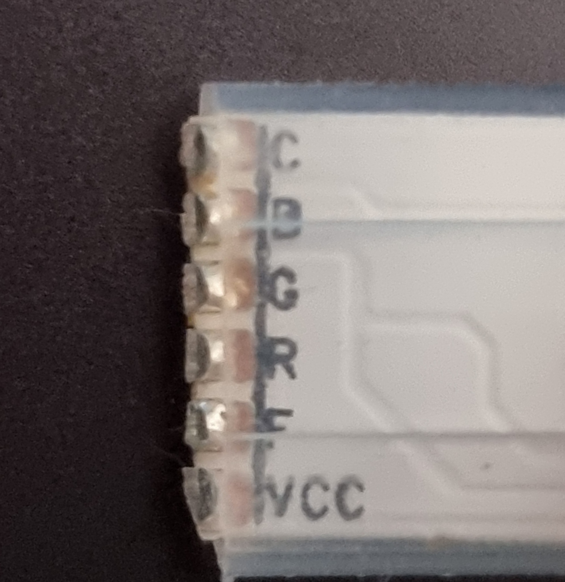
The goal is now to control the different MOSFETs with PWM of the board you're using. If you look closely at one of the two ends of the ribbon, you will notice that we have six inputs:
- C -> Cold White LED's
- B -> Blue component of RGB LED's
- G -> Green component of RGB LED's
- R -> Red component of RGB LED's
- F -> Warm White LED's
- Vcc -> +24V power
The alimentation of the MOSFET is +24V and GND of your power source, the load output corresponds to the linear interpolation based on PWM input (with limits: 255 -> GND and 0 -> +24V), thus when the PWM input for the cold white LED MOSFET is equal to 255, then the corresponding LEDs are lit at their maximum power because the F pin is now directly connected to ground, meaning that the difference between the LED strip power source and the F pin is:
I think you understood that with a PWM value of 128, the differential voltage between the power source and the pin is
You can use any PWM outputs of your development board, just change the value in the main.cpp code :
#define RED_PIN     13
#define GREEN_PIN   12
#define BLUE_PIN    25
#define COLD_PIN    32
#define WARM_PIN    26
Now you just need to wire the different transistors to the PWM outputs of your micro-controller and you should get an assembly like this:
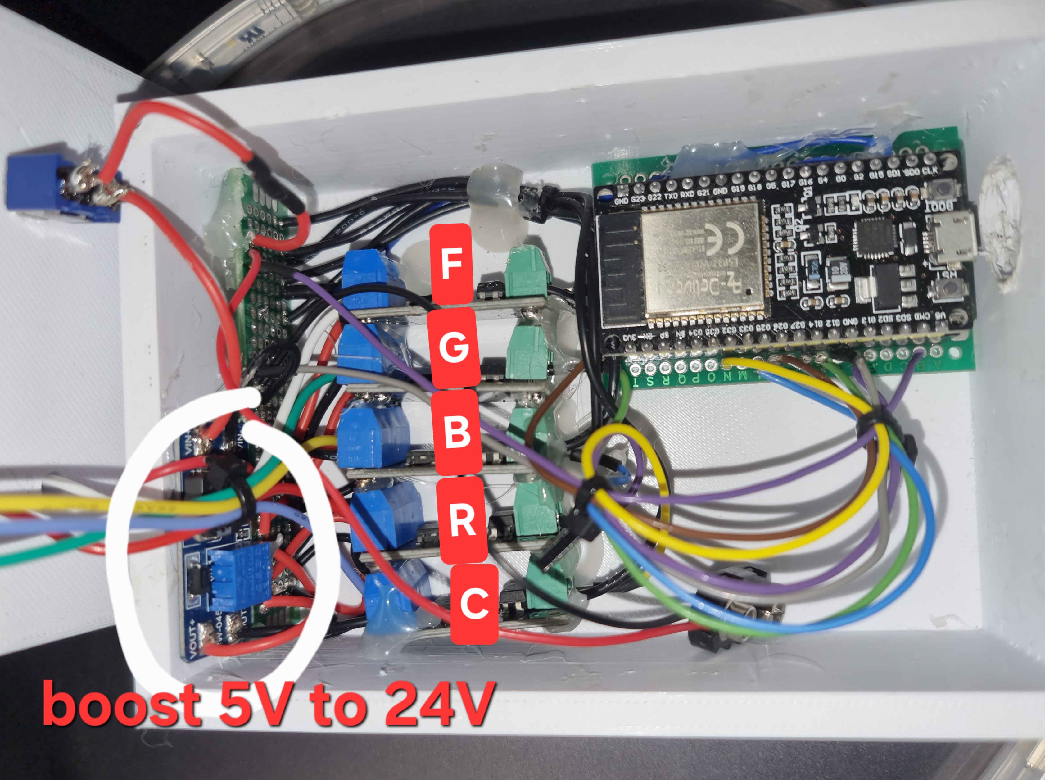
If everything is properly wired and the program is correctly flashed onto your module, all you need to do is power your board (via USB, jack, etc...). The program should initialize normally without any issues, ready to receive instructions sent by the software, which we will detail in the next section.
This section must be followed only by users who want to execute the python script instead of using the executable portable version (available in the releases page).
The following steps must be accomplished and verified before first use :
- A proper Python installation to run the
app.pyscript. - All dependencies installed :
pip install PyQt6 pybluez librosa scipy numpy sounddevice
- RGB Mode: control the RGB LEDs by specifying red, green and blue component amount.
- Cool White Mode: control the Cool White LEDs by specifying the power of LEDs (0 to 255).
- Warm White Mode: control the Warm White LEDs by specifying the power of LEDs (0 to 255).
- Wave Color: An infinite gradient of colors cycling through the entire color spectrum.
- Music SYNC: Give an .mp3 file of your favorite music and the light strip will display the perfect color (or flashing white) matching the dominant frequency each 100ms. The app plays synchronously the sound in background on your speakers.